Most images can be clicked for a larger view.
I get a surprisingly large number of questions about schematics so I thought it was time to cover that topic here.
This tutorial is meant to give you some basic skills for creating schematics in Adobe Illustrator or a similar vector based application. There are countless ways to create schematics, this is just how I like to do it. Hopefully, even if you don't have Illustrator, some of my suggestions will be useful for you if you've struggled with making your own schematics. These instructions are written by a Mac user and I am using Illustrator CS2 and CS3. I will try to provide appropriate alternatives for PC in brackets [], but no promises that they will be 100% accurate. Refer to your Help menu, if need be, for PC or older versions of Illustrator.
The first step, of course, is to open a blank document. (Once you've made a few schematics you like, you can start using the ones you've made as a template, which will save oodles of time.) I like to build the schematic to the approximate scale of the sample I am or will be knitting.
Once you have a blank document, go to the Illustrator Preferences [Options] and choose Guides and Grids.
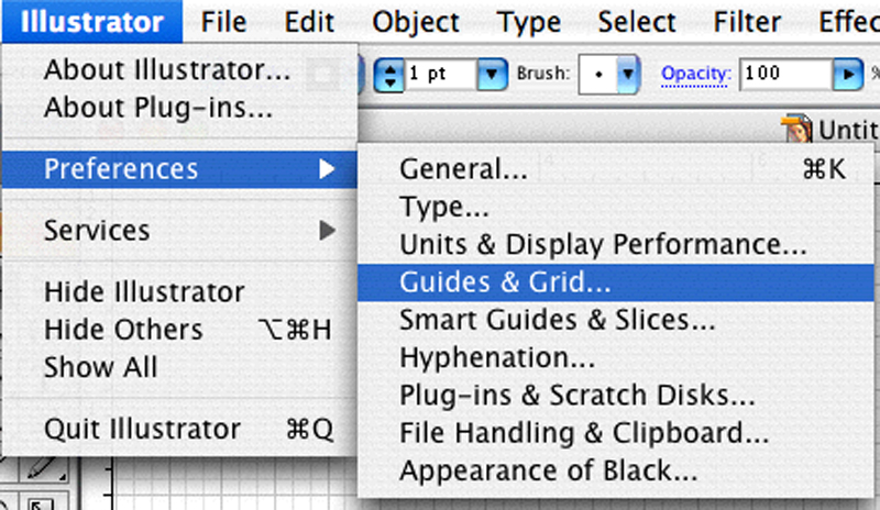
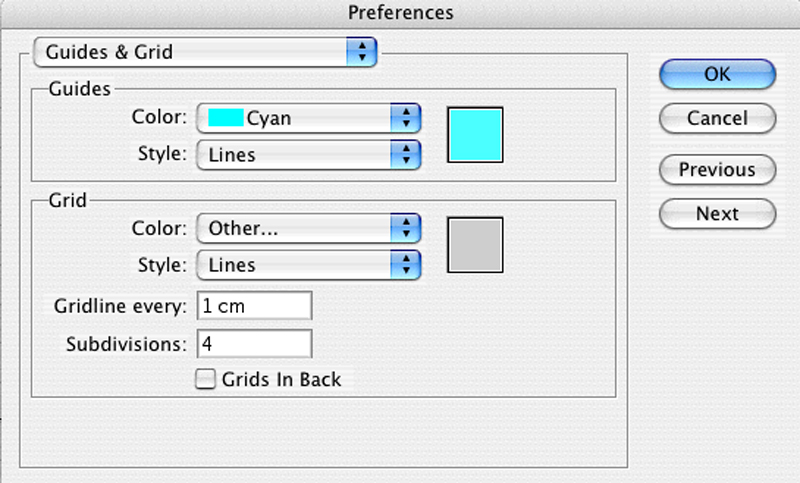
You can use whatever you like for measurements, but I find it useful to start with a centimeter per inch relationship. I set up grid lines every centimeter with 4 subdivisions each, which allow me to get quarter inch increments in my scaled down schematic.
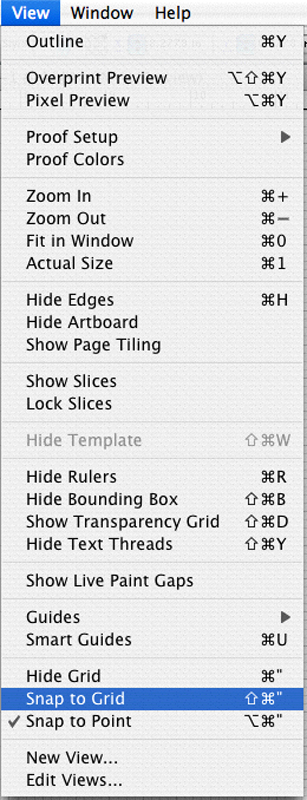
To make your grid visible, type CMND+' [CTRL+']
In the VIEW menu, choose SNAP TO GRID. This will force you to place points only on the grid you set. You can toggle this off as needed, but, when left on, it allows you to create a really precise and neat schematic.
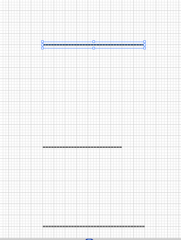
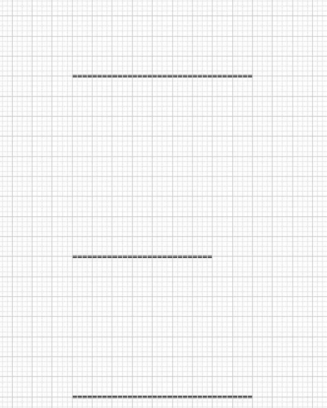
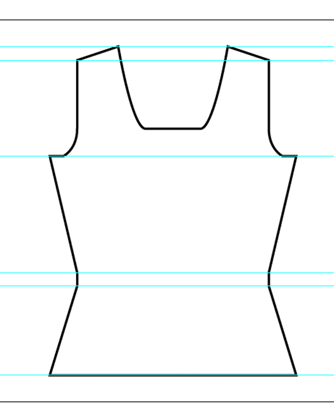
We're going to start by setting some guidelines. We'll be building just half the front, to start with. My sample has a 36" hem, so half the front will be 9" wide.

Starting from a point near the bottom middle of the page, and using your Pen
![]() tool (quick
key for Pen tool is the letter P), click a point and then click a point 9
thick grid lines over. If you hold down shift,
when you click the second point, you'll be assured of placing it in alignment
with the first point.
tool (quick
key for Pen tool is the letter P), click a point and then click a point 9
thick grid lines over. If you hold down shift,
when you click the second point, you'll be assured of placing it in alignment
with the first point.
Deselect the first line by typing CMND+SHIFT+A [CTRL+SHIFT+A] or clicking
the Selection ![]() tool and
clicking anywhere on the page. Click the Pen
tool and
clicking anywhere on the page. Click the Pen ![]() tool
again if you don't have it selected.
tool
again if you don't have it selected.
The next guideline is the waist. In this garment, the waist is 7"up from the hem and the waist is 28" around which will give us 7" wide for half the front.
The last guideline in this section will be the bust, which is 9" above the waist and the same width as the hem.
Note that the three guidelines are aligned on the left edge, which will be the center of the schematic.
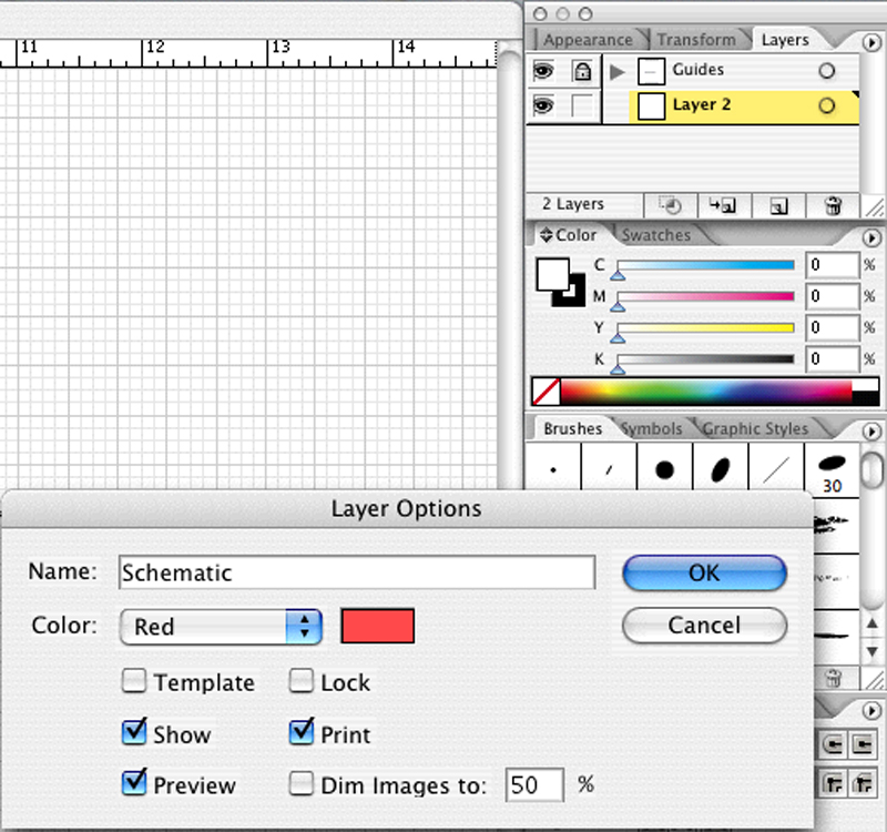
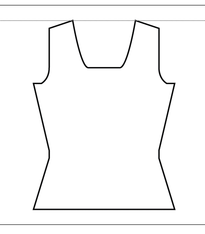
Create a new layer for the schematic and lock the one with the guides. (To lock a layer, click the box next to the eye icon in the Layers palette. A lock will appear.) If you try to do this next step, without locking the guides, you'll find that your schematic points link to your guide points and it will all be very annoying. Ask me how I know.
Grab yourself the Pen tool ![]() again
and begin at the first point you drew and trace your silhouette. I find it
useful to set a fill color and line color
again
and begin at the first point you drew and trace your silhouette. I find it
useful to set a fill color and line color![]() .
I'm doing a black line with a blue fill, but pick whatever you like.
.
I'm doing a black line with a blue fill, but pick whatever you like.
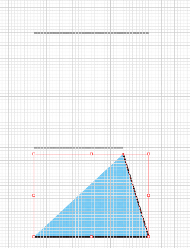
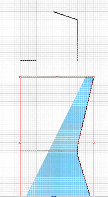
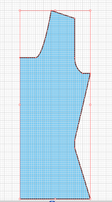
Remember that the waist is generally worked straight for about an inch, so click a half centimeter below the waist guideline.
Then click a half centimeter above the waist guideline and continue up to the chest. If your waist is a different depth, adjust accordingly.
My sample has a 1" bind off at the underarm, so I draw the next segment directly in, 1 cm.
Time to lock the schematic layer and go back to the guide layer.
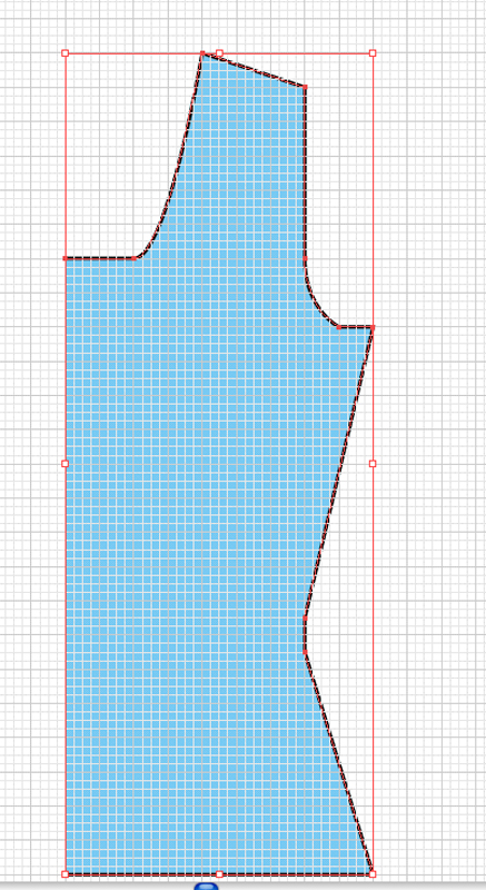
The sample armscye has to come in a total of 2" and will be a total of 7" deep, so I've placed a line to indicates that. I don't agonize over the curve of the armscye, I just like a rough approximate, so I've started this guideline about 2cm above the underarm bind off, to leave room for the curve of the armscye.
The shoulder depth is about an inch deep and the shoulder strap about 3" wide, so I've indicated that as well, on the guideline.
The last guide I've inserted is to indicate the bottom of the scoop neckline. The center neck bind off is 4" total so, from the center, I've drawn a 2 cm line.
Lock your guide layer again and go back to your schematic and click your Pen
tool ![]() . Click on the last point
of the schematic, the one that finished the underarm bind off segment. This
will make the schematic shape active again and you'll be able to add onto it.
. Click on the last point
of the schematic, the one that finished the underarm bind off segment. This
will make the schematic shape active again and you'll be able to add onto it.
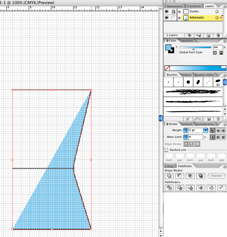
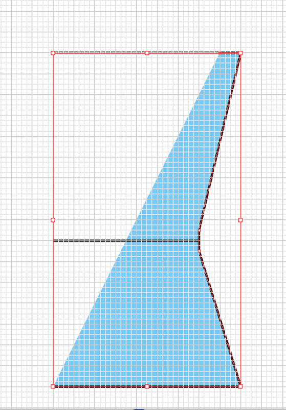
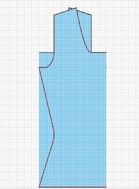
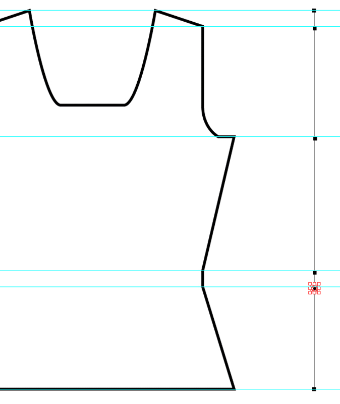
To get a really clean curved line, we'll draw a bezier curve with our pen tool. Click and hold at the top of where the curved portion of your armscye should end. Holding down shift, with the button still clicked, drag your pointer up. You'll see the curve form. Use the image below as a reference. Again, you don't have to make this particular curve absolutely accurate, you just want to mimic the curve of the armscye.
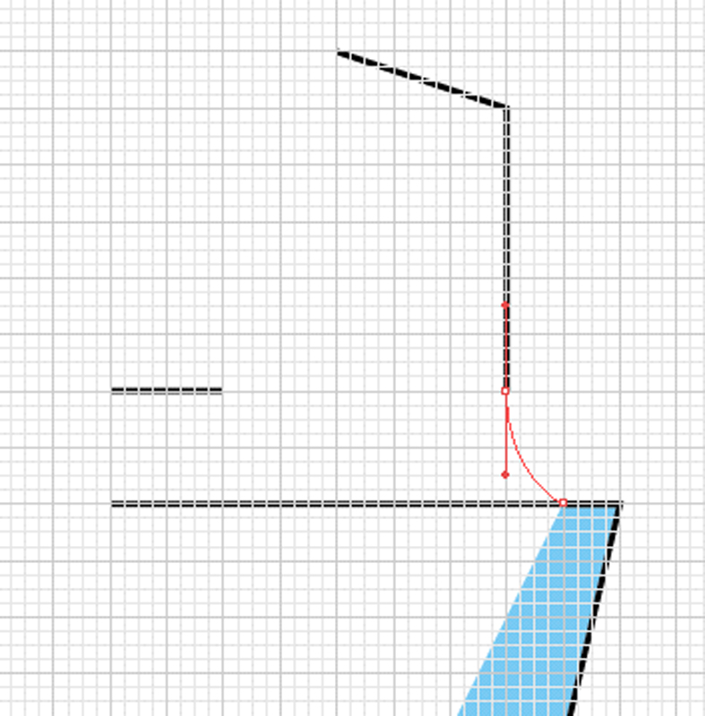
Now just finish drawing the outline to the end of the shoulder seam.
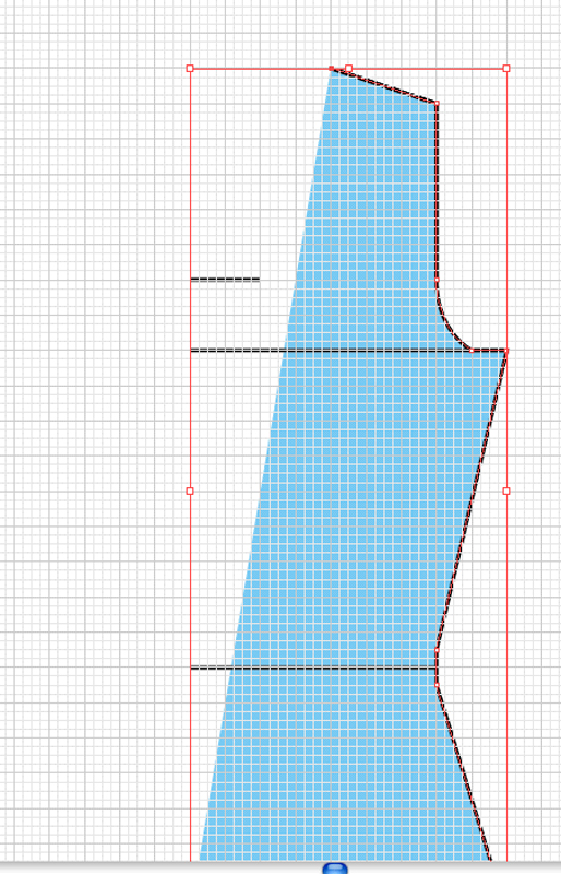
It's time to add another curve for the neckline. Click and hold on the point of the guide that indicates the edge of the neckline bindoff, hold down the shift button and pull the cursor straight to the side to mimic the curve of the neckline.

Use this same method for drawing crew necks and other rounded necklines. Use straight segments for V, square or boat necks.
Draw your last segment straight across to the center of the schematic to finish this half of the front.
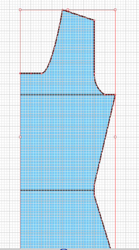
You can hide your guide layer now. To hide a layer, click the little eye icon for that layer, in the Layers palette.
Select the half schematic with the selection tool. ![]() .
.
Choose the Reflect ![]() tool
by clicking the letter O. Press Return [Enter]. This will bring up a dialog
box. Make sure VERTICAL is selected and press the COPY button.
tool
by clicking the letter O. Press Return [Enter]. This will bring up a dialog
box. Make sure VERTICAL is selected and press the COPY button.

This will make a copy of the half you made and flip it.
Go back to your SELECTION ![]() tool
by clicking the letter V. Click and hold the new flipped half and hold down
shift while dragging it into position next to the first half you drew. Holding
down shift will ensure that the two halves remain aligned (top and bottom)
while you position the halves next to each other.
tool
by clicking the letter V. Click and hold the new flipped half and hold down
shift while dragging it into position next to the first half you drew. Holding
down shift will ensure that the two halves remain aligned (top and bottom)
while you position the halves next to each other.

Switch to the Direct Selection![]() tool
and carefully draw a box with it, around the center two points of the neckline.
tool
and carefully draw a box with it, around the center two points of the neckline.
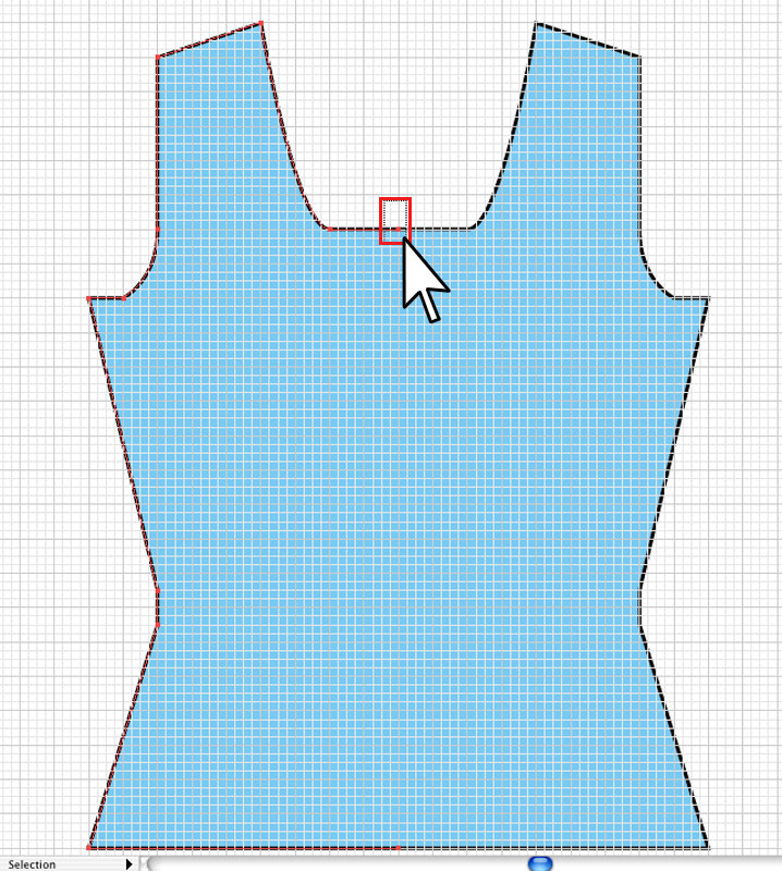
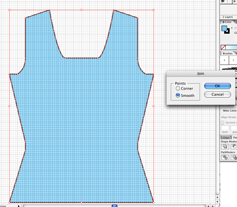
Join those two points by going to OBJECTS | PATH | JOIN or clicking CMND+J [CTRL+J]
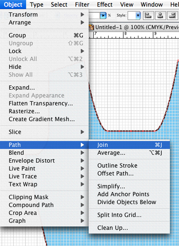
If the two points are at the exact same point, which yours should be, you'll get a little dialog box. Set it to SMOOTH and click OK. If they are slightly separated, the dialog box won't appear, which is fine.
Repeat this process at the bottom center point.
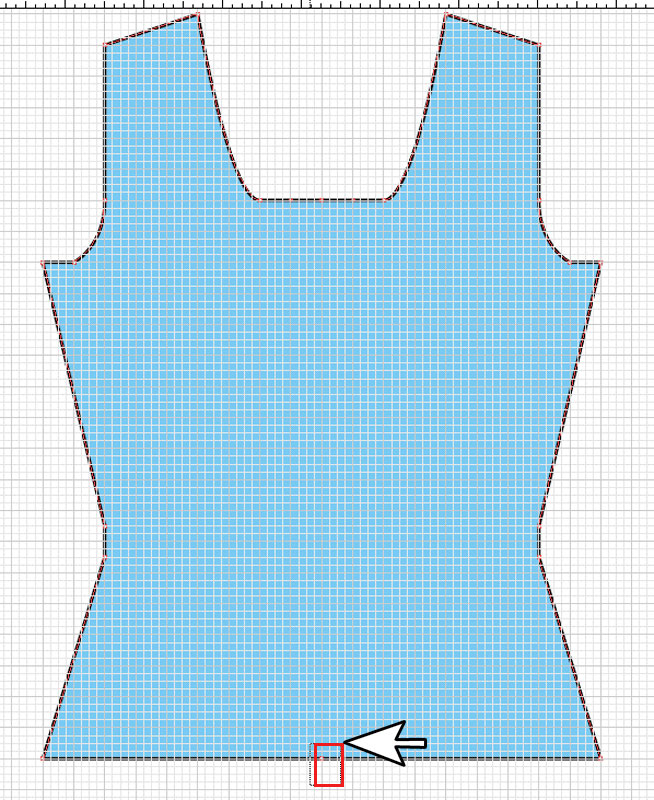
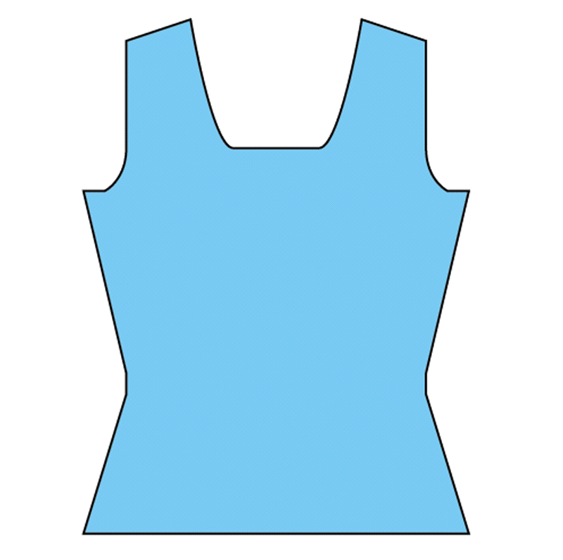
Press CMND+' [CTRL+'] to hide the grid. You now have a completely symmetrical schematic.
If you had sleeves, you would draw them the same way. For cardigans, just
omit the step of copying and joining the halves. You'll need to close the shape by using
the Pen ![]() tool to click the
last point you drew on the half and then the first point you drew for the schematic.
tool to click the
last point you drew on the half and then the first point you drew for the schematic.
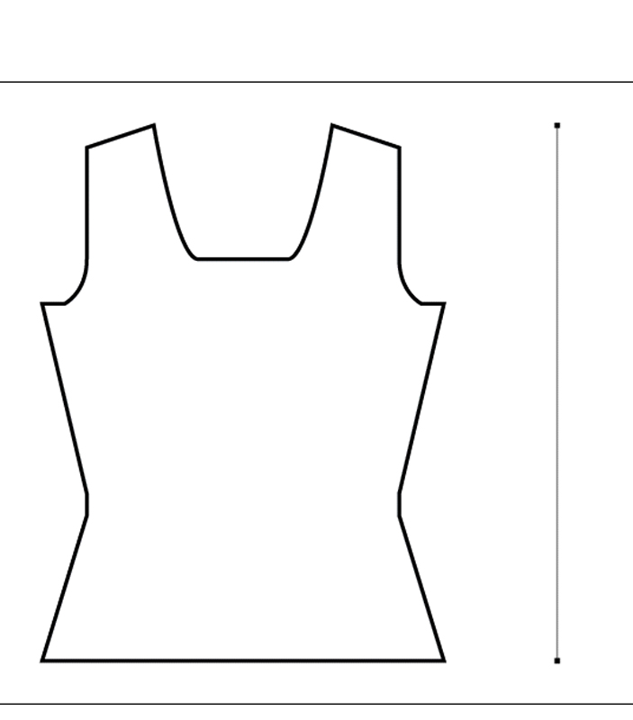
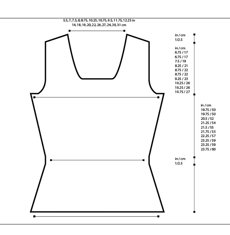
At this point, you can set the schematic's fill color to white, since that's probably how your final schematic will look, and you can adjust the stroke thickness, if you like. You want your schematic stroke to be thick enough to reproduce at a small size, so I suggest a 3-5pt thickness.
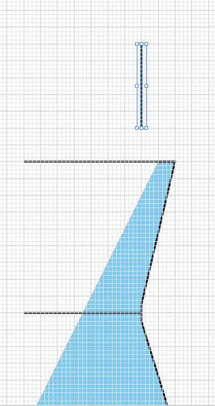
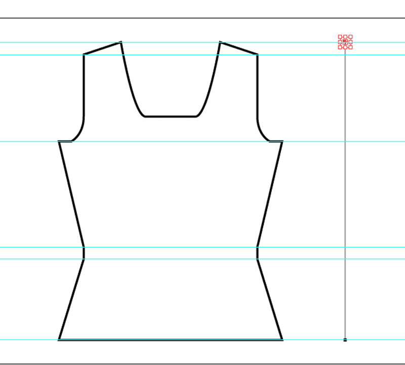
Now you'll input your measurements. Begin by dragging guides onto the page to align with each major point on the schematic. In Illustrator, you should have your Ruler CMND+R [CTRL+R] visible. Then just use your cursor to drag guides directly from the ruler by clicking and holding and releasing at the correct point.
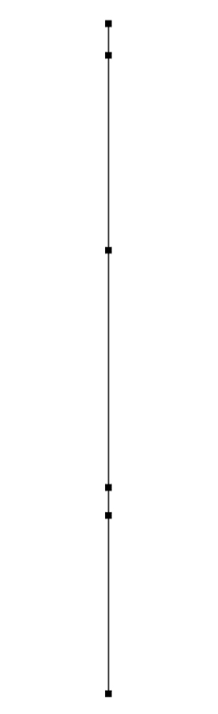
With the Pen tool ![]() , decide
where you want your first measurement line. Click in alignment with the top
of the garment and then at the bottom of the garment to indicate the length
of
the
piece.
, decide
where you want your first measurement line. Click in alignment with the top
of the garment and then at the bottom of the garment to indicate the length
of
the
piece.
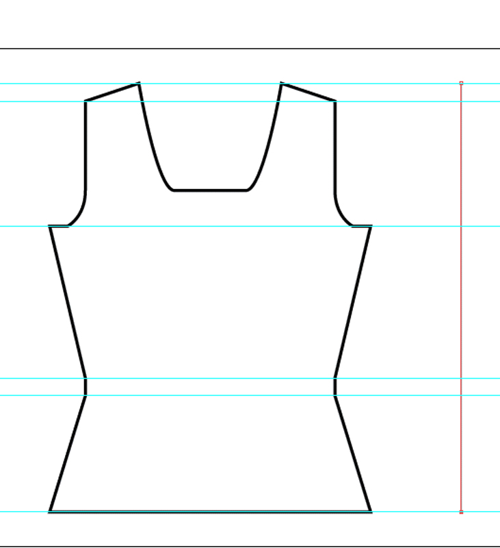
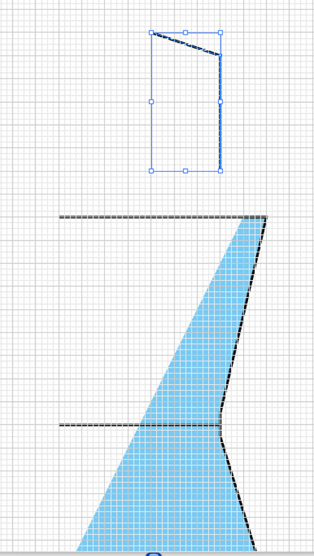
Go to the FILTER menu and choose STYLIZE | ADD ARROWHEADS
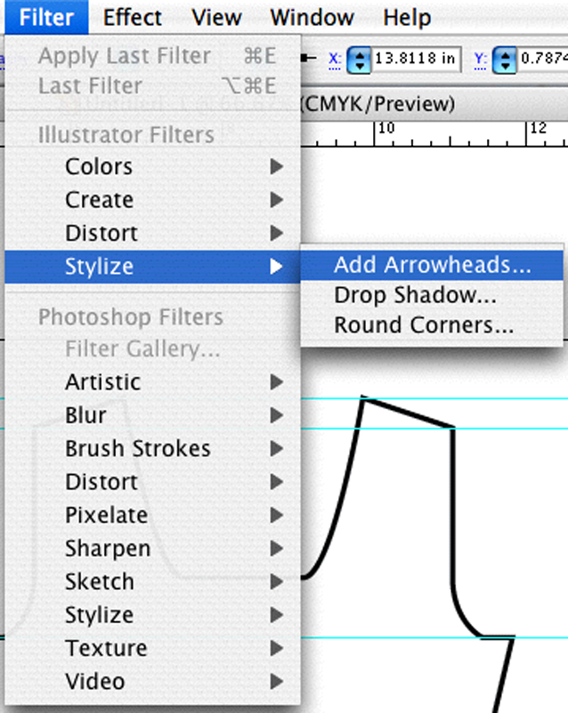
This brings up the Arrowheads dialog box.

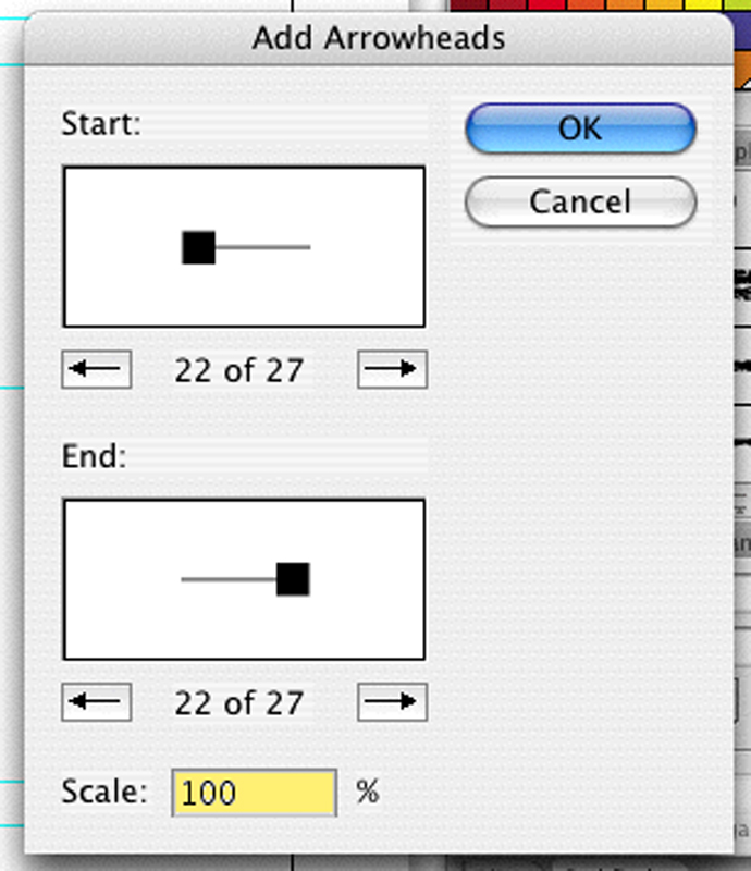
The size of the arrow heads is determined by the stroke weight of the line to which they are attached. If you find the scale unattractive, you can undo the Apply Arrowheads step then go back and pick the option again and choose a new Scale percentage in the dialog box.
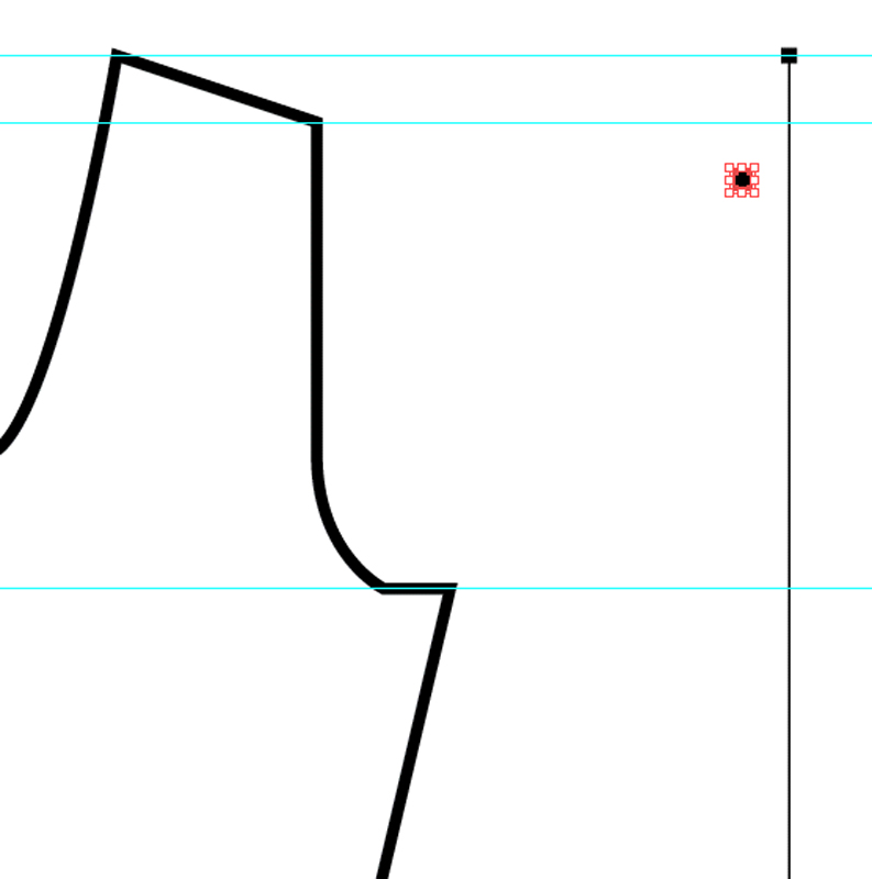
With the Direct Selection ![]() tool
click the box at the top of the line. Zoom in so you can select directly in
the center of the box. If you click the edge, you'll only select part of the
box.
tool
click the box at the top of the line. Zoom in so you can select directly in
the center of the box. If you click the edge, you'll only select part of the
box.
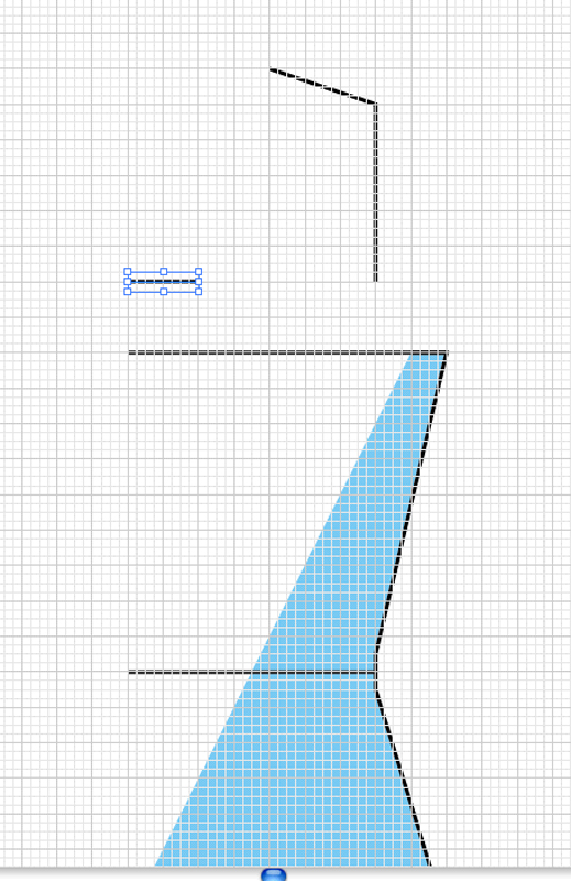
Copy and paste it for as many points as you need to add along that line, for your schematic. Some schematics only list a few measurements and some list all. It's really up to you.
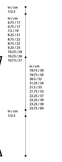
With the Selection ![]() tool,
click and drag the various boxes to the horizontal rule for each point you
want to add. Don't worry that they are not perfectly aligned along the vertical
axis, we'll fix that later.
tool,
click and drag the various boxes to the horizontal rule for each point you
want to add. Don't worry that they are not perfectly aligned along the vertical
axis, we'll fix that later.
With the Selection ![]() tool
still selected, select all the points and the line you drew. Click the center
alignment button.
tool
still selected, select all the points and the line you drew. Click the center
alignment button.

This will put all the points in alignment with each other and centered on the line you drew.
Now type in your values for this line. I keep all my calculations in an Excel document so I can just copy and paste. I round all inches to the closest quarter inch and round all centimeters to the closest full number.
We'll adjust the placement of the numbers later, as needed.
We can do the same sort of process for horizontal measurements. This time, however, you have a shortcut for putting the blocks on the end of your lines. Draw your line, Go to the FILTER menu and choose APPLY ADD ARROWHEADS. You can also simply type CMND+E [CTRL+E].
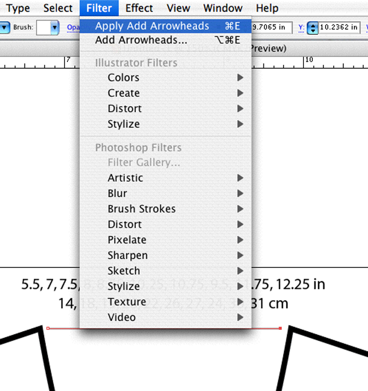
This places the exact same arrowheads you applied last time. Continue drawing in lines for your schematic and applying the arrowheads. You don't have to stack all measurements along a single line, as we did for the vertical measurements.

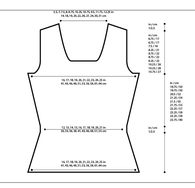
The goal is to clearly identify the various dimensions without causing confusion, so play around with your placement.
Use your alignment tools and the grid to make everything line up properly.
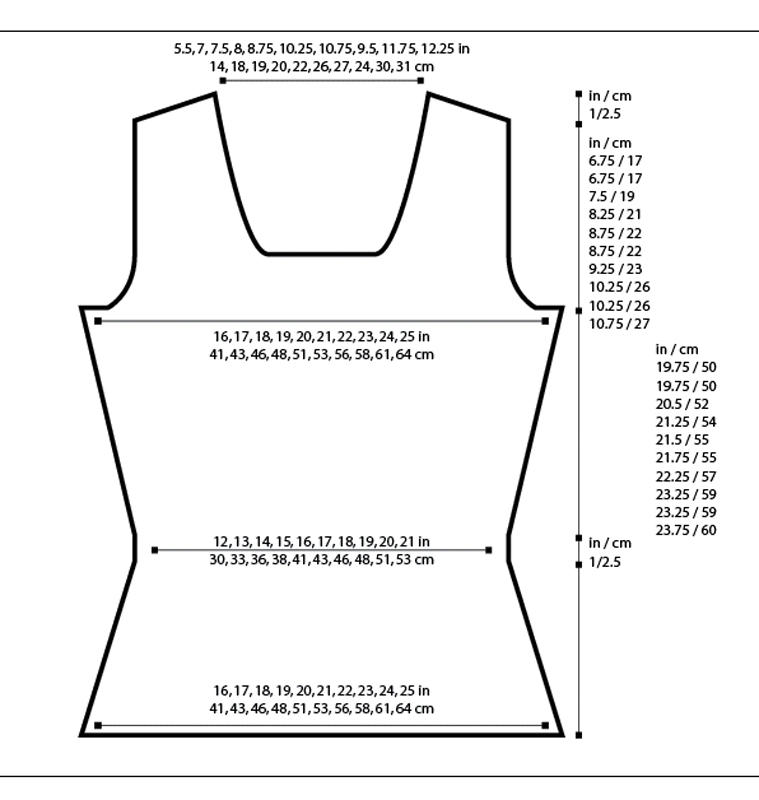
If you select everything and switch to your Text ![]() tool,
by clicking the letter T, you can adjust all the text elements at once, including
changing the font,
size, bolding, and leading. Keep in mind the size at which the graphic will
be used. Reduce your preview to about that size and change the font until it
is clearly legible. Keep in mind that your vision may be better than that of
some of your readers so err on the side of making your text larger.
tool,
by clicking the letter T, you can adjust all the text elements at once, including
changing the font,
size, bolding, and leading. Keep in mind the size at which the graphic will
be used. Reduce your preview to about that size and change the font until it
is clearly legible. Keep in mind that your vision may be better than that of
some of your readers so err on the side of making your text larger.
If you are going to be using this graphic in an InDesign file, you don't need to do anything else, just place the file in your document.
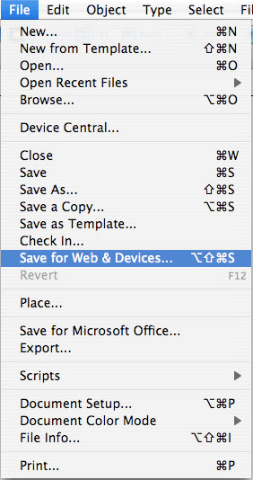
If you want to use this in MS Word or send the file to some sort of print publication, you will probably need to export a print quality graphic, like TIFF. Go to FILE | EXPORT
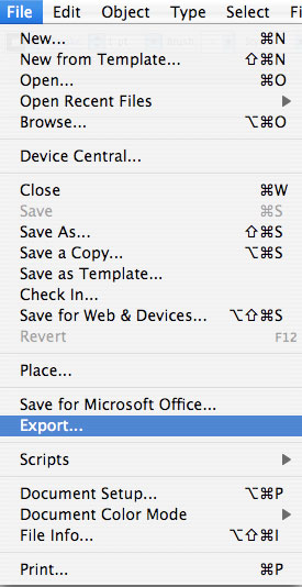
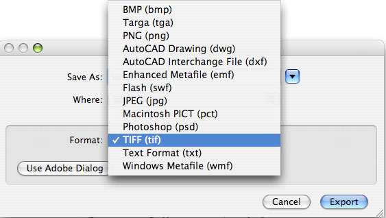
Then choose TIFF format in the file format pull down menu. JPEG is also a popular file format, because most computers and applications can open it, but the quality of the image will be lower than a format like TIFF.
For a web graphic, GIF is generally a good format for this type of artwork. You can make a web ready graphic typing CMND+SHIFT+S [CTRL+SHIFT+S], or choosing the SAVE FOR WEB option from the file menu.

Then choose GIF from the file format drop down menu and save.
Both these options will save copies of the graphic. Your original Illustrator file will remain editable and intact as a separate file. If you need to edit the graphic, you'll have to export a new copy.
That's it! If you have Illustrator, you can download a copy of the schematic by clicking here. I've saved it to be compatible with Illustrator 10 and later.
For those of you who make your own schematics (no matter the program you use) I'd love to hear your thoughts and suggestions. Please leave a comment with any tips you might want to share.
Share this post
Comments (20)
I love you. Thank you.
Posted by Elizabeth | June 4, 2008 7:33 AM
Posted on June 4, 2008 07:33
Fantastic — thank you so much for all the thought and effort you put into this valuable resource!
Posted by Zhenya | May 24, 2008 8:04 AM
Posted on May 24, 2008 08:04
When reflecting your half schematic, you can have the reflected copy automatically placed on the mirror side of the original by: placing a guide line along the center axis; use the direct select tool to select your object; click the reflect tool; press ALT first and then click on the guide. The reflect box will appear and when you click copy the new reflected half will be placed on the other side of the center guide line.
Posted by Grace | May 13, 2008 12:19 PM
Posted on May 13, 2008 12:19
I've used Illustrator for about 10 years, and I still find this extremely helpful. Snapping to guidelines? Genius! Why didn't that ever occur to me?
Posted by Melissa | May 13, 2008 11:58 AM
Posted on May 13, 2008 11:58
just wanted to let you know i posted about this on the chum. thanks for all you do for the knitting community!
Posted by minnie | May 13, 2008 5:00 AM
Posted on May 13, 2008 05:00
Thanks Bob T. and Steph (and Marnie for giving me the heads-up). I'm on Mac, but raised with UNIX-based machines and already have X11 installed, so I should be good-to-go!
Posted by AmyP | May 5, 2008 12:26 PM
Posted on May 5, 2008 12:26
Great timing - now I just need a spare minute for actually executing. No illustrator here, but as BobT said, this should work for inkscape. Gottta love the freeware.
Posted by Julia | May 4, 2008 8:20 AM
Posted on May 4, 2008 08:20
Oops, I meant xfig, not xv.
Posted by Steph | May 2, 2008 8:11 PM
Posted on May 2, 2008 20:11
Another free option is xv for Linux or MacOSX (needs X11, which comes with the Apple Developer Toolkit -- also free).
It is easy to use and can do the snap-to-grid, arrows, basic lines and shapes as in the schematic above. That said, if you are not already somewhat familiar with Linux/X11, it's not worth installing just for xv.
Posted by Steph | May 2, 2008 7:40 PM
Posted on May 2, 2008 19:40
Okay, just did it in Inkscape. It's a little different, but not too hard to figure out. The first thing is to set the grid in "document properties."
The tools are similar, but most of the keyboard shortcuts won't be the same. It does have a status bar on the bottom, telling you what modifiers you can use and what they'll do.
I kind of limped through it, haven't done vector editing in 10 years or more.
Posted by Bob T | May 2, 2008 5:24 PM
Posted on May 2, 2008 17:24
The GIMP is raster-based. If you're using Linux or Windows, try Inkscape for vector images.
Posted by Bob T | May 2, 2008 4:35 PM
Posted on May 2, 2008 16:35
Awesome tutorial - I wonder if it will work for GIMP? (God, I hope that doesn't get caught in a spam filter!)
Posted by AmyP | May 2, 2008 6:53 AM
Posted on May 2, 2008 06:53
Wow! Thanks for sharing this tutorial! I've really learned a lot and can't wait to go home and try it out! :)
Posted by Ruinwen | May 2, 2008 6:41 AM
Posted on May 2, 2008 06:41
Oh, must show Mum. She uses Photoshop at work. Thanks for the detailed instructions :)
Posted by Ginger aka Beethoven | May 2, 2008 6:03 AM
Posted on May 2, 2008 06:03
Illustrator and InDesign are seriously my two best friends. This is pretty close to exactly how I create basic illustrations as well.
Posted by TheBon | May 1, 2008 5:57 PM
Posted on May 1, 2008 17:57
Oh, thank you thank you thank you!
Posted by Sarah | May 1, 2008 5:33 PM
Posted on May 1, 2008 17:33
This is super cool - thanks!
Posted by Sarah L. | May 1, 2008 5:04 PM
Posted on May 1, 2008 17:04
Wow Marnie..this looks like a really useful tutorial...thanks so much! I don't have illustrator but may need to invest. I currently do a pretty poor job on appleworks drawing. It does the basics for me but is limited....I'm also not that good at doing the whole to scale stuff..slowly getting better I think!
Posted by Gudrun | May 1, 2008 2:10 PM
Posted on May 1, 2008 14:10
wow you are a goddess. thank you so much for sharing all this knowledge. I've been using your other tutorials for making charts in excel. thank you a million times.
Posted by kat | May 1, 2008 2:06 PM
Posted on May 1, 2008 14:06
wow. thanks for such an awesome tutorial.
Posted by winnie | May 1, 2008 1:09 PM
Posted on May 1, 2008 13:09